Comparing Underground Natural Gas Storage With Deep Saline Injection Of Carbon Dioxide


Public opinion regarding the effects of climate change has evolved steadily over the last decade; recent surveys typically indicate that most Americans believe more needs to be done to offset its effects. Indeed, this change has altered the political landscape, and it now seems likely the federal government will maintain—and perhaps increase—the incentives for companies to reduce their greenhouse gas (GHG) emissions.
Because fossil fuels, particularly natural gas, are expected to continue to play a significant role in electricity generation, achieving GHG emissions reductions will require the large-scale deployment of carbon capture and sequestration (CCS) technologies.
The injection of carbon dioxide (CO2) into deep saline aquifers is expected to be the most deployed technology for achieving carbon sequestration. Because carbon sequestration is only beginning to be implemented in large-scale projects, it makes sense to look to an already commercialized analog industry on which companies seeking to develop carbon sequestration sites can leverage their experience.
Underground natural gas storage is a useful analog to deep saline injection of CO2, and the purpose of this paper is to briefly compare the two applications from a petroleum engineering perspective.
Operational Objectives
There are three overall objectives for designing and operating a natural gas storage reservoir: (1) accessing the desired storage capacity; (2) preventing gas migration; and (3) developing and maintaining desired gas deliverability. These objectives align very well with the objectives of CO2 storage; ensuring sufficient capacity, demonstrating, and monitoring containment, and ensuring sufficient injectivity to minimize the number of injection wells. The phases of project development and operation of the two project types reflect the similarity of their operations (Figure 1).
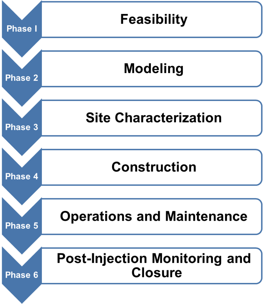
Project Feasibility & Modeling
The feasibility and modeling phases ensure that the reservoir is suitable for capacity, containment, and injectivity. The components of an ideal natural gas storage site include a porous and permeable formation overlain by an impermeable seal.
Core analysis, wireline logging, seismic surveys, and comparison to analog reservoirs are used to determine the geologic parameters needed for ascertaining the suitability of the reservoir for storage. Because depleted oil and gas reservoirs represent 80% of active natural gas storage facilities in the U.S., these reservoirs have typically been penetrated by many wells and ample reservoir and petrophysical data are available.
READ MORE: Carbon Capture Rising
Most underground CO2 storage capacity in the U.S. is in saline formations, however. Therefore, these reservoirs may have no prior wellbore penetrations and lack extensive reservoir data. In those cases, seismic and analog reservoir data can be used in the feasibility stage.
For underground gas storage, shallow reservoirs are typically preferred. This reduces the cost of drilling the wells and reduces the pressures required for injection. Carbon dioxide storage sites, however, require a minimum reservoir depth of 2,600 feet to keep reservoir pressures high enough to maintain the injected CO2 as a supercritical fluid to maximize storage capacity.
During the feasibility and modeling phases, many of the engineering techniques used are very similar, although there are some differences. For example, natural gas and CO2 have very different fluid properties, which must be considered through appropriate equations of state. Also, because an element of long-term deep saline storage is trapping the CO2 in the reservoir at residual saturation, those projects require greater information of the relative permeability characteristics of the reservoir.
Site Characterization
Following the feasibility and modeling phases, data is acquired to build additional models and reservoir simulations in the site characterization phase. Methods of data acquisition include seismic and well logging, core analysis, and injectivity tests. This data is submitted during the permitting process to demonstrate the suitability of the storage site to the appropriate regulatory agency.
Under the Safe Drinking Water Act of 1974, the U.S. Environmental Protection Agency (EPA) has authority to regulate the underground injection of fluids, but an amendment to the Act excludes natural gas storage facilities. The EPA’s Underground Injection Control Program regulates the construction, operation, permitting, and closure of injection wells, with CO2 injection wells for long-term storage denoted as Class VI. Each CO2 injection well requires its own permit and five plans are required to acquire a Class VI permit:
- Area of review and corrective action plan.
- Testing and monitoring plan.
- Injection well-plugging plan.
- Post-injection site care.
- Site closure plan, and emergency and remedial response plan.
The regulatory agency with jurisdiction over an underground gas storage site depends on whether the facility is designated as “interstate” or “intrastate”. For instance, interstate facilities are regulated by the Federal Energy Regulatory Commission (FERC) while intrastate facilities are regulated by state agencies. FERC regulators deferred to state agencies in 1997 following the Research and Special Programs Administration issuance of Advisory Bulletin ADB-97-04, which concluded that natural gas storage requirements would be tailored by a state’s geology and hydrology.
As a result, natural gas storage regulations vary by state. The natural gas storage permitting process is like the CO2 permitting process in its focus on protecting the environment and demonstrating that the storage zone is secure, but the process is lengthier for CO2 storage projects.
Construction
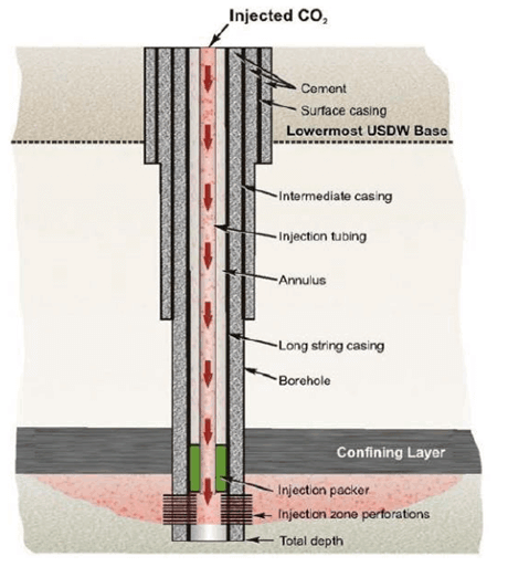
Construction begins following the acquisition of the necessary permits. In addition to injection wells, infrastructure for natural gas storage sites includes monitoring wells, extraction equipment, pipelines, dehydration facilities, and compressors. Additional infrastructure for CO2 storage sites includes pipelines and monitoring wells. Carbon capture infrastructure construction coincides at the emission site during this step. The EPA’s requirements for the construction of Class VI wells are detailed below and depicted in Figure 2.
- Surface casing must extend through base of lowermost underground source of drinking water (USDW) and be cemented to the surface.
- At least one long string of casing with centralizers from surface to injection zone and cemented back to the surface is required.
- Tubing and packer with appropriate materials suitable for CO2 service.
- Annulus between tubing and long string casing must be filled with a non-corrosive fluid.
- Continuous recording devices must monitor pressure, flowrate, volume/mass, and CO2 stream temperature.
- Alarms and shut-off systems may be required.
Additional seismic, well logging, and core samples must be acquired once a CO2 injection well is completed. If the data correlates with the submitted plans, the EPA authorizes CO2 injection. A Monitoring, Reporting, and Verification (MRV) Plan must then go into submission within 180 days of injection.
Operations & Maintenance
The operations phase includes operational planning, site preparation, and monitoring. Well integrity testing and monitoring wells ensure that the natural gas and CO2 are not leaking from the storage reservoir. The EPA requires the following during CO2 injection operations:
- Continuous and periodic well integrity tests.
- Analysis of CO2 stream.
- Continuous monitoring of pressure, flow rate, and volume.
- Corrosion monitoring on a quarterly basis.
- Monitoring of groundwater quality and geomechanical changes above the confining zone(s).
- Monitoring of the CO2 plume and the associated pressure changes.
- Description of the Area of Review at a minimum of every five years during operation, including the projected movement of the CO2 plume and formation fluids.
Post Injection Monitoring & Closure
Site closure begins following the completion of the injection. Activities include injection equipment removal, plugging of injection wells, and beginning site restoration work. As with the other elements of the carbon sequestration process, post-injection monitoring is specific to each CO2 storage site. Monitoring wells are utilized along with reservoir models to track the pressure of the CO2 plume.
READ MORE: What Does IRS, Treasury Carbon Capture Tax Credit Guidance Mean For Future Energy Production?
The EPA dictates that post-injection monitoring must occur for 50 years unless it approves an application for reduction or it establishes non-endangerment, which occurs once the CO2 plume pressure reaches a certain level. Once the process reaches a non-endangerment status, the plug-in of monitoring wells starts, monitoring equipment is removed, and the surface is reclaimed.
Conclusions
In addition to the notable difference of permanent versus temporary storage, certain reservoir characteristics and the regulatory agencies differ for natural gas and CO2 storage. The exemption of natural gas storage sites from EPA regulation coupled with the experience of the natural gas industry results in a less rigorous regulatory process for natural gas storage compared to CO2 storage.
While these differences are important to note, underground gas storage remains an important and useful analog as CO2 storage transitions from its current state to large-scale deployment.
Related Insights


Our experts are here
for you.
When you choose Opportune, you gain access to seasoned professionals who not only listen to your needs, but who will work hand in hand with you to achieve established goals. With a sense of urgency and a can-do mindset, we focus on taking the steps necessary to create a higher impact and achieve maximum results for your organization.
LeadershipGeneral Contact Form
Looking for expertise in the energy industry? We’ve got you covered.
Find out why the new landmark legislation should provide a much-needed boost for the development of carbon capture.